
JAMES M. BENSON and CHARLES E. HAWK
Hastings-Raydist. Inc
A mass flow meter can be used for a rapid check of the orifice diameter of small nozzles in production. The use of critical flow makes the test independent of pressure downstream of the orifice.
Small orifices and nozzles of the types used in gas burners, oil burners, spray guns, and expansion throttles of refrigeration machines are manufactured to tolerances that may be difficult to hold in routine production unless sample units are regularly inspected for accuracy of the drilled holes. Probably the most satisfactory method of inspecting these orifices is to establish a flow through the hole under a given set of conditions that are accurately known and to measure the resulting flow. The method described here makes use of a sensitive flowmeter comprising a compensated thermopile to measure the critical flow* of air through the nozzle. The airflow through the orifice can readily be established at the velocity of sound; this condition is easily reproduced with simple equipment that is well suited to routine testing. The method and equipment have proven particularly well adapted to the measurement of orifices having diameters ranging from 0.002″ to 0.010″, but are not limited to that range.
CRITICAL FLOW
When gas flows through a nozzle or orifice, the flow depends on the pressure differential across the orifice only up to a certain point. If the upstream pressure is held constant and the pressure at the discharge end is decreased, the flow of gas will increase up to a critical value. Beyond this point further decrease in the downstream pressure causes no further increase in inflow. This is the critical flow condition. (It is related in a simple way to the velocity of sound in the gas, which in turn depends on the molecular weight and ratio of specific heats of the gas, as well as the temperature.)
When air flows through a nozzle, the critical condition is obtained if the upstream pressure is approximately two or more times the downstream pressure. The equation for critical flow through a nozzle is:
q = CApK √ MU/T (1)
where q is mass rate of flow of the gas; C is discharge coefficient; A is the cross-sectional area of the nozzle throat; p is upstream static pressure of the gas; K is dimensional coefficient involving the gas constant; M is the molecular weight of the gas; T is the absolute temperature of the gas upstream, and U is a constant that is characteristic of the gas equal to: k[2/(k+ 1)]8, in which k is the ratio of specific heats (Cp/Cv) and s =(k+1)/(k—1).
For airflow, this equation becomes:
q = 0.53 CpA/√T (2)
where q is the flow rate (lb/sec), C is discharge coefficient, p is pressure (psia), T is absolute temp ( ̊R), and A is nozzle area (sq in).
A vacuum pump can be connected to the discharge end while the upstream end of the orifice is open to the atmosphere. The upstream pressure, p, is then barometric pressure; T is the absolute temperature of the atmospheric air entering the nozzle.
If the barometric pressure and the ambient temperature are constant, the flow (q) then depends only on C and A. Although much experimental data have been published for orifices having diameters of the order of 1″ and more, data for commonly used small orifices having diameters of the order of a few thousandths of an inch are more limited. However, some tests on several small orifices assembled from commercially available sapphire-cap bearing jewels ranging from 0.0024″ to 0.044″ diameter have been described.[2] On those tests the discharge was measured at a pressure ratio of approximately 3 to 1, assuring critical flow. Variations of 10% in the downstream pressure resulted in no measurable change in discharge. Variations in the upstream had a linear effect on the discharge, in accordance with theory. Although the cap-bearing jewel is not designed as a nozzle, the contour of the orifice does resemble that of a nozzle and would be expected to have somewhat similar discharge characteristics.
Several “standard” sets of atmospheric conditions are in use. One standard, which has the advantage of being near the conditions usually found in a shop environment, specifies a temperature of 75 ̊F (534.9 ̊R) and a barometric pressure of 29.99″ Hg (14.73 psia). At these standard conditions, and for a nozzle coefficient of unity, the computed mass flow rate of air is20.2 pounds per minute per square inch of nozzle area.
For actual nozzles made according to ASME standards, coefficients of between 0.92 and 0.97 are common. The coefficient for thin-edged orifices may be as low as 0.6.
Equation (2) can be rewritten as a function of the orifice diameter. The volume flow in cubic centimeters per minute of air at standard temperature and pressure becomes:
V = 6.0 a²
where a is the diameter in mils (0.001”). Table 1 lists numerical values used in estimating the range of flowmeters suitable for testing various sizes of nozzles.
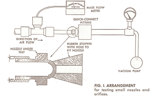 Equipment and Procedure