Hydraulic systems that must operate in extremely small spaces often demand more performance per pound than heavy-duty systems many times their size.
Power density refers to how much power a system or assembly transmits within a prescribed envelope. High power density is among the most useful characteristics of hydraulic systems. The pressurized fluid contained within hydraulic cylinders can move loads weighing thousands of pounds quickly and accurately — all with an almost effortless pivot of a control lever or joystick.
When components become miniaturized, high power density becomes more difficult to maintain, even if systems operate at higher pressures. If hydraulic systems did not operate at high pressure, they would lose their high-power-density advantage, and a competitive technology — such as an electro-mechanical system — may be used instead. However, higher pressures generally require stronger, heavier-duty components. This necessitates thicker walls and piston rods, which works against the goal of miniaturization.
Smaller size: bigger challenges
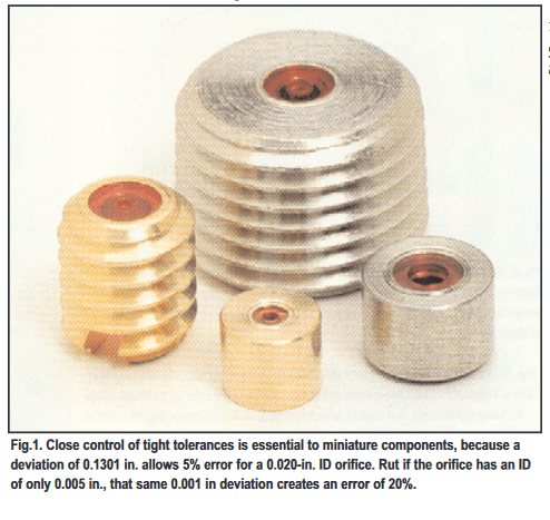
Cutting a component’s size does not necessarily reduce friction by a proportional amount. So as components become smaller, higher pressures and flows are required to generate the same power per unit of volume as with the larger component. For example, seal friction usually increases as a result of higher operating pressure. This means doubling pressure to a cylinder will not quite double its thrust. On a more basic level, decreasing the diameter of a circular piston reduces surface area exponentially. However, only a linear reduction in circumference occurs. And because piston seal contact area is a function of circumference, decreasing the size of a cylinder increases seal friction in proportion to thrust. Internal leakage also contributes to power loss. If the same clearances are used for a miniature cylinder as in a larger cylinder, more flow is lost to internal leakage in the miniature cylinder. This internal leakage can degrade not only actuator speed but thrust as well. Consequently, miniature components must be manufactured with very tight tolerances to maintain high operating efficiency and performance. But manufacturing components with tighter tolerances increases cost. Moreover, the reduced clearances of these components require more intensive filtration to keep contamination particles from clogging up, jamming, or damaging miniature components.
Higher performance without the higher cost
The solution to these challenges would seem to be simple: miniature components will cost more money. This is true in many cases, especially when components must be custom-designed. These special cases may involve:
- making components of the highest strength materials available
- employing the most sophisticated manufacturing techniques
- machining components to tolerances in the hundredths of thousandths of an inch, and
- specifying the highest performance filtration systems available.
However, most designers try to avoid specifying custom-designed components for the simple reason of economy. Fortunately, a number of manufacturers incorporate innovative techniques to provide the high performance required by miniature systems without sending costs through the roof.
Orifices provide consistent precision

A poor choice of materials of construction further complicates orifice performance, continues Baillio. Even if a steel or brass orifice is manufactured consistently with high precision, these materials can quickly wear, again affecting their Cd. This is especially important with the higher operating pressures often associated with miniature hydraulic systems because wear accelerates as pressure increases.
Baillio suggests a wire lapping method as an alternative to conventional orifice machining. This method involves cutting a pilot hole in an orifice blank, then threading a wire through the pilot hole. Introducing a diamond slurry as the wire is pulled through the hole produces orifices with tolerance variations of 0.0002 in. with extremely sharp edges and a mirror-like surface finish of 2 μ-in. In addition to producing very precise orifices, the process is also economical, because thousands of orifices are threaded and lapped at a time. Using a synthetic ruby material ensures high wear resistance even at pressures to 20,000, explains Baillio. The synthetic nature of the ruby makes the orifices economical, and mounting them in a variety of standard configurations makes them economical for a wide range of applications. Their consistency from one orifice to another means that they don’t have to be installed as pairs to provide balanced performance.
Mountings and configuration
Sometimes taking advantage of unconventional mountings and configurations is all that’s needed to substantially reduce the envelope of components. For example, bottom-ported cylinders, Figure 2, eliminate having to locate hoses and fittings near the cylinder barrel. In this configuration, fluid entering one port flows directly into the cylinder’s cap end. Fluid entering the other port passes through an internal channel and enters the head end of the cylinder. The cylinder itself is not any smaller than a conventional one, but relocating hoses and fittings to the cap end of the cylinder frees up space at the “business end” of the cylinder. Taking this concept a step further, bot-tom ported cylinders can even be mounted in a manifold, Figure 3. Cartridge mounting completely eliminates the need for hose, tubing, and fittings to be connected directly to the cylinder. This technique mirrors the same advantages enjoyed by cartridge valves: economy, reduced potential for leakage, compact design, and a simpler, neater package.
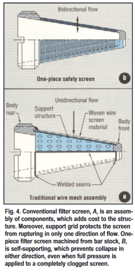
Protecting critical components


