
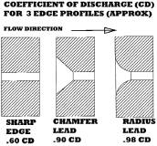
Figure 1. Source: Design Engineers Handbook, Parke Bulletin 0224-B1, Pg. g-9
To produce True Sharp Edge Orifices®, all the variables that might influence the Cd Value (Coefficient of Discharge) must be controlled during production. This includes the orifice hole length, edges, surface finishes, roundness and the elimination of all tool marks, burrs, ragged edges and irregularities. If any one of these areas is not perfectly managed, the orifice flow rates will vary from piece to piece, thereby making it impossible to predict flow with any accuracy. See Figure 1: Cd for 3 Edge Profiles (Approx).
Figure 1 illustrates that changing the edge profile of a Sharp Edge Orifice will result in large fluctuations in Cd values. A True Sharp Edge Orifice® has a Cd value of .60. Introducing a chamfered edge can boost Cd to as much as .9 and introducing a radius may result in Cds up to .98. This illustrates how significant small alterations in orifice edges can be.
Chamfers and radiuses are even more difficult profiles to repeat in production. Chamfering or radiusing the orifice edge introduces more variables than a simple sharp edge. In a sense, you have added another set of edges and surfaces into the equation. As a result, the .9 and .98 values will be hard to maintain repeatedly. Sharp Edge Orifices with a Cd of .6 are preferred by engineers because they are a simple profile and more consistent if produced correctly.
Precision machine drilling of near perfect Sharp Edge Orifices is next to impossible. Drilling inherently can be a brute process of cutting metal to generate a hole. Drills leave behind spiral tool marks, burrs, poor surface finish and out of round or elliptical holes due to drill wobble. If the burrs are removed by chamfering then, as illustrated above, the Cd value is altered. If they are not removed, then you have ragged edges. It is a catch 22. Secondary procedures, such as electro polishing, while helpful, cannot remove all the irregularities that are created by the drilling process.
Because of the pitfalls of drilling, many manufacturers resort to individually flow checking each orifice. This can be labor intensive and expensive. The smaller the orifice, the more difficult it becomes to produce large quantities of repeatable orifices.
Keeping an orifice edge sharp after it is installed can be a critical issue, especially in high-pressure gas and liquid applications that can wear down the effective edge. If the instrument has been calibrated, it may now significantly undervalue the flow once the edge begins to radius from wear or damage1 . This is why orifices need to be made of hardened and durable materials to reduce the wear factor. Making a True Sharp Edge Orifice® and keeping it is vital to maintaining flow settings of the instrument it is installed in.
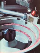
Figure 2.
True Sharp Edge Orifices® are successfully being produced economically by a non-traditional three-step process using a combination of laser drilling and wire lapping, in conjunction with surface lapping. Ruby is the material of choice since it is next to diamond in hardness, yet economical. This is a man-made crystal grown from alumina powder, which is melted at high temperature to crystallize on a seed crystal to form a single crystal of either ruby (which is red because of a chromium .05% dopant) or clear sapphire (no dopant) that is almost chemically inert, 9 mohs hardness (diamond being 10), with five times the abrasion resistance of carbide. Some applications in water jet cutting approach 40,000 psi using sapphire orifices. Where other materials, such as hardened steel, would quickly erode away, the sapphire keeps its edge under such extremes for a longer duration.
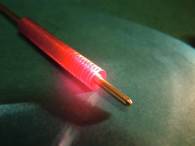
Figure 3.
Figure 2 illustrates the ruby blanks being vibratory fed to the laser for piercing. This is the best method for quickly getting through this hard material.
Figure 3 illustrates how the pierced ruby blanks are strung thousands at a time on long tapered wires. The wires are then connected to two large spools. The spools slowly advance the taper in an oscillating motion through the strung rubies using fine diamond slurry until the exact size orifice is achieved. The resulting holes are all identically round. Imparted from the roundness of the wire, they all will have a 2 micro inch polished surface finish or better. Diameter tolerance within a lot will vary less than .0001”, and overall tolerances of .0002” are the norm.
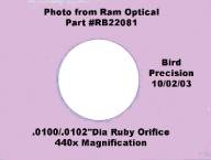
Figure 4.
The final finishing operation is face lapping both sides of the orifice to both control the orifice throat length, as well as achieve the desired sharp edges. The faces will also have a 2 micro inch finish. The result of this three-step process is a True Sharp Edge Orifice®. The Cd values will almost be identical, since all the variables that could influence them are controlled. The orifice edges will remain sharp longer in applications of high pressure, chemical or abrasive conditions. See Figure 4: .0100” Orifice 440X Power.
Thousands of cloned Sharp Edge Orifices are simultaneously and economically produced in sizes from .0016” and up. They are easily inserted into a variety of stainless brass or plastic fittings, connectors or inserts.
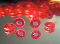
Figure 5. Finished Ruby Orifices
True Sharp Edge Orifices® find application in analytical instruments, gas chromatographs, gene splicing tools, medical gas metering, chemical metering, sand blasting nozzles, critical flow restrictors for sampling instruments, pace makers, anesthesia orifices, nitrous oxide boosters, ink jet printers, leak detection masters, water jet and various pneumatic regulator and hydraulic restrictor applications. See Figure 5: Finished Ruby Orifices.
Bird Precision of Waltham, Massachusetts produces True Sharp Edge Orifices® exclusively by this three-step process and stocks over 140 unique sizes, along with an assortment of standard filtration and mounting options.
Bird Precision welcomes your visit to www.birdprecision.com, where you can learn more about these True Sharp Edge Orifices®, or your call at 1-800-454-7369.